
Images Processing
Summary:
As the first cloud-based step for personalization, provide the data via the File Picker: either a T1-weighted MRI for an isotropic model, a zipped file containing T1, DTI, bval, and bvec files for an anisotropic model, or — when using the Offline Personalization workflow — the anonymized zip archive produced locally by run_personalizer.bat. After uploading, specify the electrode geometry and whether to register a detailed atlas to the brain; click Start to generate the anatomical model. See Data Quality Requirements for input file specifications.
Once uploaded, the user can specify the geometry of the electrode, and if the head should be registered to the ICBM_152 atlas for cortical structures. By clicking start, the anatomical model is generated. Computational time is approximated to be ~1h, and can increase to ~2.5h if cortical atlas registration is selected. The computation is done when a tick-icon appears on the previously pushed start button. The user can go to the next step by pressing the arrow on the right.
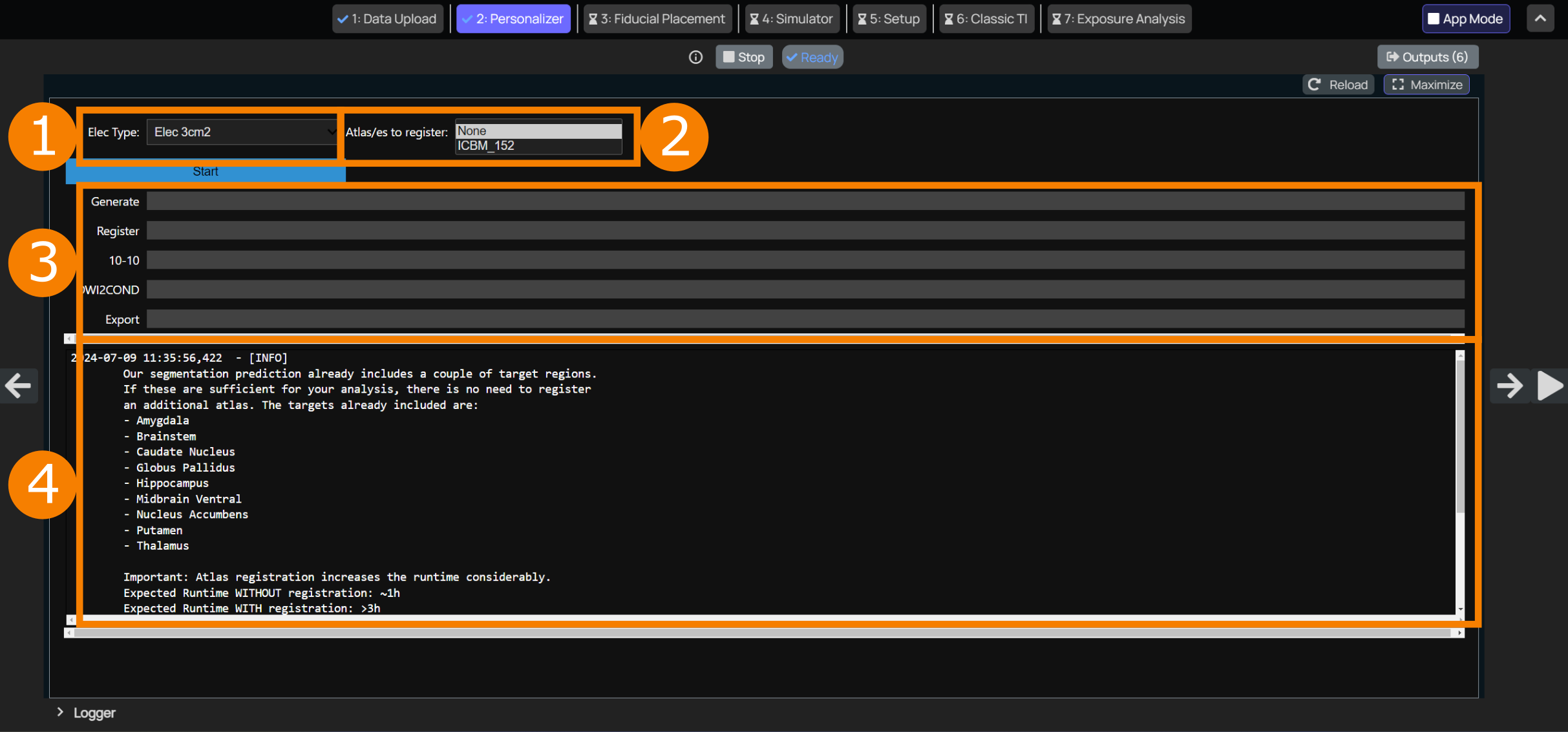
The interface has the following elements:
Select Electrode Radius
The radius of the cylindrical electrodes is selected here. This can only be changed as long as no simulations have been started in Simulator.
Select Atlas to Register
By default, the model prediction already contains a couple of targets. These are listed in the logger (4) in the image above. If these are sufficient, you can leave this setting at
None. If not, a detailed atlas can be registered to the brain. Select the according option. Since this is a multi-select list, please make sure thatNoneis not selected together with the atlas to register, because the registration will always be skipped ifNoneis selected.DTI Processing Options
Specify how the DTI data should be processed:
- Turn the registration of the DTI to MRI T1 on or off. This option is only appropriate, when the two acquisitions differ by minor translations with no rotations involved. If a rotation is required, the b-vectors will no longer correspond to the rotated DTI volume.
- Turn Denoising of the DTI on or off
- Select, whether to cap the b-values, and if yes, at what level. Finally, the tool allows you to select the model used to extract the diffusion tensor (
auto,dti,dki). Thedtianddkimodel are explained in the table below.autowill selectdkiif the number of non-zero b-value shells is bigger or equal two, otherwise it will select thedtimodel.
Label Tooltip Reference DTI Fits a second-order diffusion tensor assuming Gaussian diffusion. Best suited to low-to-moderate diffusion weighting; estimates may become biased when non-Gaussian diffusion is significant at higher b-values. Basser PJ, Mattiello J, LeBihan D. MR diffusion tensor spectroscopy and imaging. Biophys J. 1994;66:259–267. DOI: 10.1016/S0006-3495(94)80775-1. (PubMed) DKI Extends DTI to account for non-Gaussian diffusion by jointly estimating the diffusion tensor and a kurtosis tensor. Typically requires multi-shell data and higher diffusion weighting. Jensen JH, Helpern JA, Ramani A, Lu H, Kaczynski K. Diffusional kurtosis imaging: The quantification of non-Gaussian water diffusion by means of magnetic resonance imaging. Magn Reson Med. 2005;53:1432–1440. DOI: 10.1002/mrm.20508. (Wiley Online Library) Progress Overview
Shows the progress of each individual step in the model generation.
10-10will only be done if the Model Inspector step has already been completed.Logging
Provides some information about this step at start-up and will display information and eventual errors during runtime.
You can now click to the arrow on the right side of the browser to move to Model Inspector.
Fallback: Manual Electrode Placement
With TIP V4.0 and later, electrode placement on the 10-10 system is performed automatically by the Personalizer after automated fiducial detection. The step below only applies if the automated placement fails and fiducials were placed manually in the Model Inspector.
After the fiducials were placed and exported in the Model Inspector, return to this page (Images Processing) using the left arrow and click the Start button again. This re-runs the Personalizer, which now reads the exported fiducials from the .sab file to automatically position electrodes on the 10-10 system. Once the placement finishes successfully, press the right arrow to return to the modeling GUI and re-import the model — it will now include the full 10-10 electrode system.
Verify the electrode placement in the viewer. If electrodes are misplaced or have an undesired orientation relative to the scalp, try re-doing the fiducial placement in the Model Inspector.
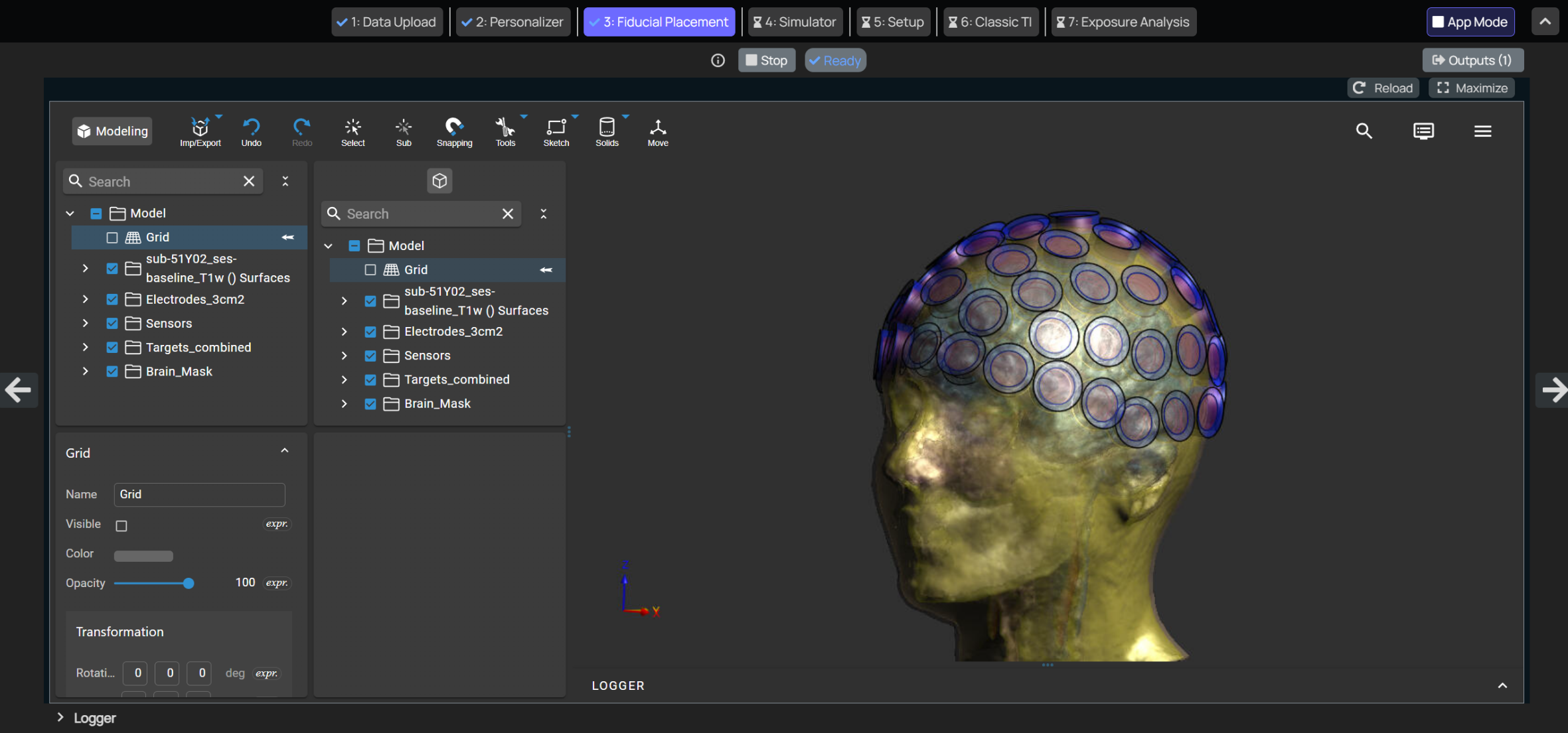
If an error occurs during electrode placement, possible causes and workarounds are:
- Verify accurate and consistent placement of fiducials according to the standard.
- Reduce electrode diameter for smaller circumference heads.